We work for your numerical simulation and software development needs.
As a widely accepted numerical method, finite element analysis (referred to as FEA) was
firstly developed and quickly got matured in the 1960's. Intensive mathematical work on convergence studies
was carried out in the two decades that followed.
 In mechanical analysis, using FEA to solve field problems, components of mechanical
variables such as displacements and stresses are considered piece-wisely distributed and the solid structure
under analysis is discretized into small regions, named "elements." In each individual of these elements
the mechanical variables are assumed continuous and represented by certain polynomial functions or other
smooth functions, called "interpolation functions." At the adjacent edges of the elements, especially the corner
points that are referred to as "nodal" points, the variables are set equal and these conditions or requirements are
called the "compatibility conditions." As the number of elements increases, the discretized mechanical system
approaches the reality.
In mechanical analysis, using FEA to solve field problems, components of mechanical
variables such as displacements and stresses are considered piece-wisely distributed and the solid structure
under analysis is discretized into small regions, named "elements." In each individual of these elements
the mechanical variables are assumed continuous and represented by certain polynomial functions or other
smooth functions, called "interpolation functions." At the adjacent edges of the elements, especially the corner
points that are referred to as "nodal" points, the variables are set equal and these conditions or requirements are
called the "compatibility conditions." As the number of elements increases, the discretized mechanical system
approaches the reality.
Commercial codes started to appear in the market in early 1980's. The worldwide
popular codes are ANSYS, ABAQUS, NASTRAN, SDRC/I-DEAS, ADINA, LS-DYNA and so on, for mechanical
, civil, and geotechnical engineering analysis. Lately, other software or interface software are developed
to tackle the requirements of special engineering problems. In particular, Coventorware, Cadence,
IntelliSuite, and more recently, Capa, are made to solve multi-physics and sensor design problems.
 Commercial codes are mostly general solvers and robust, yet may have certain
advantages and drawbacks when they are used to solve different problems. Likewise, intelligent handle
of each particular problem is essential to grant quality FEA results. A few primary concerns when
performing an FEA practice are listed in the following.
Commercial codes are mostly general solvers and robust, yet may have certain
advantages and drawbacks when they are used to solve different problems. Likewise, intelligent handle
of each particular problem is essential to grant quality FEA results. A few primary concerns when
performing an FEA practice are listed in the following.
Mesh study is essential to assure convergence and mesh-independence. A test with two
subsequential mesh schemes is minimum for this study. The finer mesh should be obtained by re-meshing
the coarser mesh and stress solutions ought to be within the allowable error range of designed stresses.
Modal analysis is often used for this test as solutions from different mesh schemes are easy to compare.
Thin shell elements are recommended for thin structures while thickness change over the
structure is gradual and loads or constraints are not concentrated. Otherwise, parabolic brick
element with 27 nodal points is suggested to better capture large stress gradient when 1. the structure
thickness varies rapidly at some points; 2. there is concentrated load or constraint and the stress distribution
in those regions are of special interest.
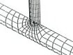
Sharp notches are to be avoided in engineering designs. However, in case such notch
can not be avoided, special concerns are necessary to assure reliable FEA solution. As a general rule, one
should use fine element
mesh around sharp notches. Elements should not be ill-shaped, that is, element corner angles
should be within the range of 45-110 degrees. Although some commercial codes have made large
element aspect ratio being allowable (some can tolerate this ratio being as high as 100 before the codes start to
complain), we suggest not to have the ratio to exceed 4 to capture stress gradient in the corresponding directions.
Electro- and magneto-mechanical analysis require rational solution schemes to obtain effective
computational results. As a mechanical structure deforms, electric or magnetic field changes and causes the
electro or magneto-mechanical load to vary accordingly. Such a multi-physical problem should be solved
by certain numerical iteration loops, and at the end of each step, all physical components, including field
variables and the moving boundary, should reach a stabilization before the structure being further loaded.
